UART INTERFACING WITH PIC
The UART serial communication is a preferred option due to its ability of long distance communication with error detection capability
Synopsis

The operation and description of the PIC18F4550 microcontroller to UART serial interface is discussed in this application note. In addition, information for obtaining the source code in C language, containing communication routines between the core microcontroller PIC18F4550 and the UART is provided.

The serial communication is a preferred option due to its ability of long distance communication with error detection capability. The implementation of a microcontroller such as PIC18F4550 to UART serial interface and the UART to RS-232 serial port interface.

Description

The function of the Main Loop is to reset and initialize the UART by writing a character (an 8-bit data) to the UART register. Inside the Main Loop, the microcontroller PIC18F4550 can select one of the two methods for communicating to the UART. The two methods are polling the UART regularly and using an interrupt handler in the interrupt service routine. If using the interrupt handler, the PIC18F4550 microcontroller and the UART interrupt bits must be enabled. The other function is to keep checking the event flags and pass to the appropriate subroutine for further processing.

Interrupt Service Routine (ISR)

The PIC18F4550 microcontroller uses the interrupt service routine to handle an interrupt generated by the UART. As soon as the UART generates an interrupt, the ISR checks the interrupt status of the UART to determine the interrupt type and sets up proper event flags to inform the Main Loop program for processing the interrupt.

UART layer

The UART layer handles the bus interface between the microcontroller and the UART. The three functions in the UART layer are:

UART-Reset - The PIC18F4550 microcontroller resets the UART device

UART-Read - The UART places a character on the data bus for the microcontroller to read and the microcontroller stores the character.

UART-Write - The PIC18F4550 microcontroller places a character on the data bus for the UART to read.

Asynchronous Communication

In this type of communication, both Transmitter (Tx) and Receiver (Rx) work on different clocks which means that they are not synchronized. Start and Stop bits are also sent with each Data byte to identify the data.

Registers of EUSART

To use the EUSART of PIC18f4550 microcontroller following registers need to be configured.

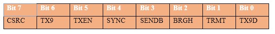
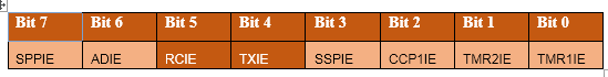
1. TXSTA (Transmit Status and Control Register)


TRMT: This is a read only bit which shows the status of Shift register where data is stored.

1 = Transmit Shift Register Empty

0 = Transmit Shift Register Full

BRGH: This bit is configured to decide the speed of Asynchronous serial communication.

1 = High speed

0 = Low speed

SYNC: The mode of communication is selected by this bit.

1 = Synchronous mode

0 = Asynchronous mode

TXEN: This bit is set to high to enable the transmission

TX9: This bit is set to high while sending 9-bit long data.

1 = Selects 9-bit transmission

0 = Selects 8-bit transmission

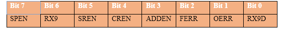
2. RCSTA (Receive Status and Control Register)


CREN: This bit is set to high for continuous reception enable. To stop reception the bit is set to zero.

RX9: This bit is used when 9-bit long data is to be received.

1 = Selects 9-bit reception

0 = Selects 8-bit reception

SPEN: This bit is used to enable/disable the serial port. (Tx and Rx pins)

1 = Serial port enabled

0 = Serial port disabled

3. TXREG (EUSART Transmit Register)

The data to be transmitted is stored in TXREG register.

4. RCREG (EUSART Receive Register)

The data to be received is stored in RCREG register

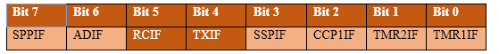
5. PIR1 (Peripheral Interrupt Request Register 1)


TXIF: This is transmitter interrupt flag bit. It becomes high when the TXREG register is empty.

RCIF: This is receiver interrupt flag bit. It becomes high when the RCREG register is full.

6. PIE1 (Peripheral Interrupt Enable Register 1)


TXIE: This bit is set to high to enable the transmission interrupt.

RCIE: This bit is set to high to enable the reception interrupt.

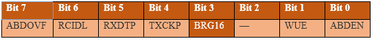
7. BAUDCON (Baud Rate Control Register)

This register controls the baud rate and some special functionalities of serial communication like auto-baud rate detection, inversion of receiving data etc.


BRG16: This bit is used to enable/disable 16-bit baud rate register.

1 = 16-bit Baud Rate Generator (BRG) – SPBRGH and SPBRG

0 = 8-bit Baud Rate Generator (BRG) – SPBRG only

This means if the BRG16 bit is set to high, the baud rate is decided by both SPBRGH and SPBRG registers; and if it is set to low, only SPBRG register will set the baud rate.

8. SPBRG & SPBRGH (EUSART Baud Rate Generator Register Low Byte and High Byte)
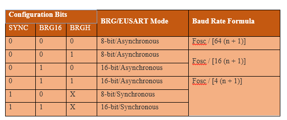
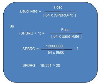
These registers are used to set baud rate for the serial communication. The two registers SPBRG & SPBRGH store lower byte and higher byte respectively.

Baud Rate:

The baud rate is the speed of data in serial communication. It is also known as bits per second (bps). PIC’s EUSART provides different communication modes like asynchronous, synchronous, high-speed and low speed etc. The baud rate for different EUSART modes can be decided by different formulae. The following table shows the baud-rate formulae for


Here :

x = Doesn’t matter

Fosc = Crystal frequency

n = Value of SPBRGH- SPBRG Register pair

For example, if a Baud rate of 9600 is to be set for a 12MHz crystal and the mode is 8-bit, Asynchronous, then,

SYNC=0, BRG16=0 and BRGH=0 and the baud rate can be calculated, by using the following formula, as given below.


Applications

• GPS

• Modem

• Wireless communication

• Bluetooth modules

Proteus design for UART interfacing with PIC


Orcad design for UART interfacing with PIC


UART interfacing with PIC

/*  Name     : main.c
 *  Purpose  : Source code for UART Interfacing with PIC18F4550.
 *  Author   : Gemicates
 *  Date     : 2017-06-23
 *  Website  : www.gemicates.org
 *  Revision : None
 */


#include<xc.h>                   // Header file for PIC18F4550
#define _XTAL_FREQ 12000000      // 12MHz

#pragma config FOSC = HS         // Oscillator Selection bits (HS oscillator (HS))
#pragma config WDT = OFF         // HW Disabled - SW Controlled
#pragma config WDT = OFF         // HW Enabled - SW Disabled
#pragma config BOR = OFF         // Brown out reset disabled<br><br>#pragma config BOR = SOFT       // Brown out reset controlled by SBOREN<br><br>#pragma config BOR = ON_ACTIVE  // Enabled when the device is not in SLEEP, SBOREN bit is disabled<br><br>#pragma config BOR = ON         // Brown out reset enabled, SBOREN bit is disabled
#pragma config LVP = OFF         // Low voltage programming mode OFF
#pragma config LVP = OFF         // Low voltage programming mode ON
#pragma config CPD = ON          // Data EEPROM Code protection ON
#pragma config WRTD = OFF        // Data EEPROM Write protection OFF
void main()                            
{
 TRISC7  = 1;                    // RC7(RX) configured as i/p                           
 TRISC6  = 1;                    // RC6(TX) configured as o/p                   
 TXSTA   = 0X20;                 // Transmission Enable(TXEN=1,SYNC=0,BRGH=1)   
 RCSTA   = 0X90;                 // Rception Enable (SPEN=1,CREN=1)             
 BAUDCON = 0X40;                 // Baudrate control Register                   
 SPBRG   = 0X12;                 // 9600 brgh=0                                 
 TXREG   = 'E';                  // Load the character to be transmitted         
 while(TRMT);                    // Wait here till transmission is complete     
 while(1)
 {
  if(RCIF==1)                    // Set when a character is received            
  {
   RCIF=0;                       // Clear Receive interrupt flag bit            
   RCREG = TXREG  ;              // Retransmit the received character           
   while(TRMT);                  // Wait here till transmission is complete     
  }
 }
}
 

Error message here!

Show Error message here!


Forgot your password?

Error message here!

Send OTP

Error message here!

Show Error message here!


Lost your password? Please enter your email address. You will receive a password you Need.

Send Error message here!


Back to log-in

Close